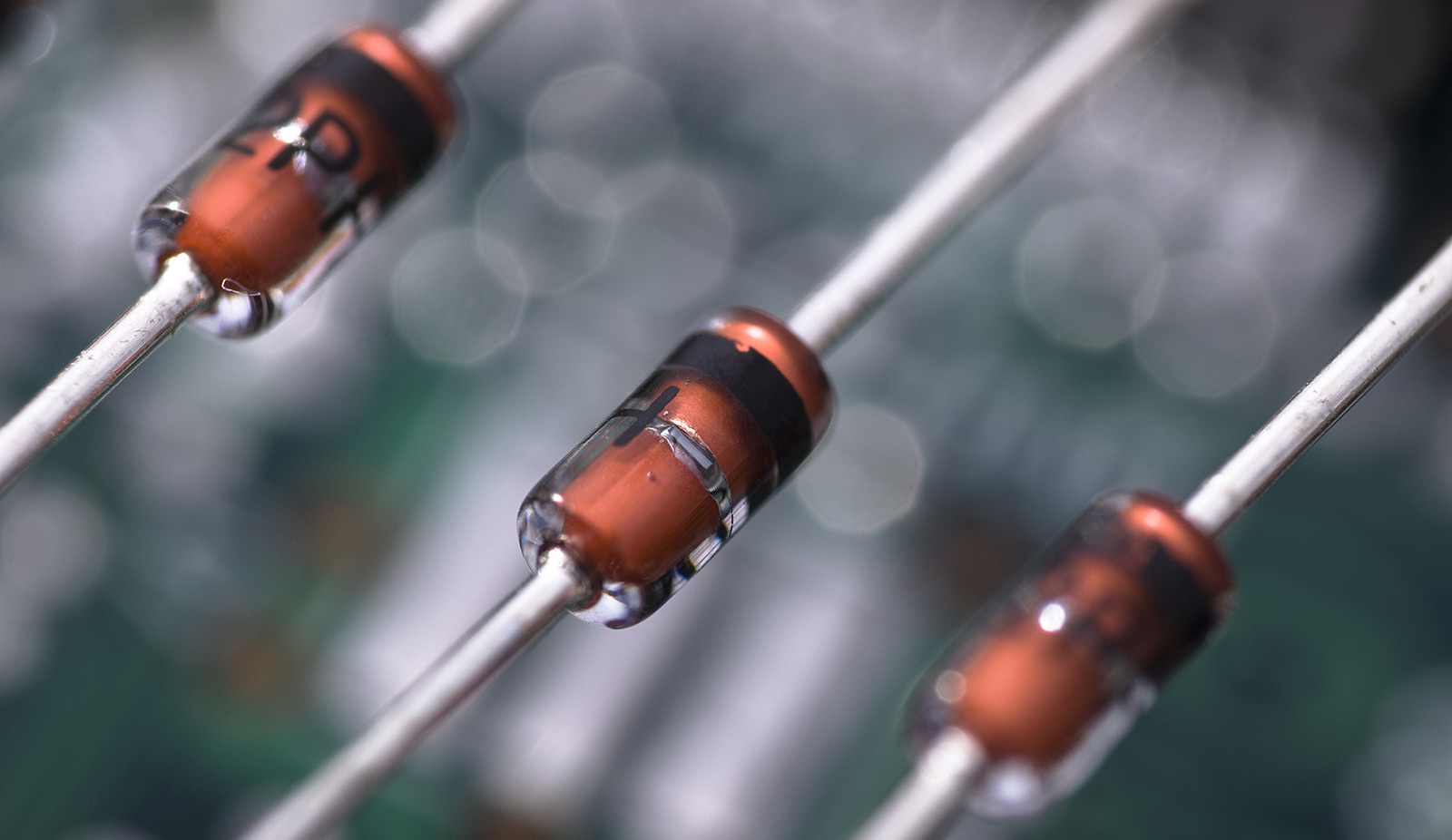
How to make a simple voltage regulator using Zener Diode
Introduction-
A zener diode is a silicon semiconductor electronic device that allows current to flow either in forward or reverse direction.
It is a special type of diode that is capable of working in reverse biased conditions. The voltage at which the diode allows the current to flow in reverse bias system is known as the Zener Voltage or Breakdown voltage.
For more info on Zener Diodes Click here.
Zener diode as a voltage regulator-
One of the major application of zener diode is Voltage regulation.
To make a simple voltage regulator using zener diode, you need these components.
1. Zener Diode ( known Zener voltage)
2. Current limiting resistor
3. Input power supply
4. Connection wires and PCB.
The circuit schematic for voltage regulation using zener is given below-
In the above circuit the R1 resistor is used to limit the current flowing through the zener diode.
It is necessary due to the limited power dissipation by a zener diode. For example, If a zener diode has zener voltage of 12V and power dissipation of 1W then the maximum current should be less than 1/12 Amps.
In the above experiment, 5.1V voltage regulation is performed.
Note- We cannot connect load with higher current consumption, as the current through the circuit is limited.
Input voltage is 15v


No comments